scotto@acm.org
This paper written
while the author was affiliated with:
Center of Excellence in Command,
Control, Communications and Intelligence (C3I)
George Mason
University
4400 University Drive
Fairfax, VA 22030-4444
The paper originally appeared in:
ACM SIGSOFT Software
Engineering Notes, 1990, 15(5), 50-59
Many experts in software engineering agree that the emerging
iterative requirements engineering, software engineering and software design
methodologies present excellent ways to identify and validate user requirements.
These methodologies often include innovative techniques for elicitation and
validation of user requirements including various forms of human engineering
analysis, rapid prototyping, and knowledge acquisition tasks. This paper
addresses the compatibility of these techniques with DoD-Std-2167A. Assessment
is made regarding the compatibility of the standard with innovative requirements
techniques, and how and where these techniques may be inserted into the life
cycle.
1.1 Why Iteration?
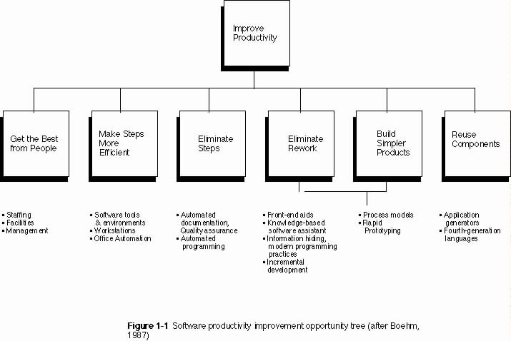
According to Boehm (1987), many opportunities exist for
improvements in software productivity. To illustrate this point, Boehm developed
a hierarchy he refers to as his "software productivity improvement tree". This
hierarchy outlines six major ways in which opportunities for software
productivity gains exist. They are to:
Figure 1-1 is a complete illustration of Boehm's tree, and the techniques associated with each major item on the tree. Notice that two major items, eliminating rework and building simpler products, have underlying techniques in common. One point that Boehm makes is that improved process models and rapid prototyping techniques aid software engineers and developers in eliminating rework during the development life cycle. Rework may be reduced or eliminated by using a process model to force project managers to focus on difficult issues during requirements and design, rather than on delivery of some required documentation. Prototyping helps to eliminate rework by insuring that requirements are
validated prior to software design, code and unit test. In addition, Boehm suggests that rapid prototyping helps developers to develop simpler products by eliminating those
features which are not valid user requirements, and which contribute to software "gold-plating". He asserts that improved process models, especially those which are risk-driven, can also help to focus software developers on users' mission objectives and contributions which additional software features lend to those objectives.
Further support can be found for the general view that improved process models and rapid prototyping techniques help to improve software productivity. For example, Sage and Palmer (1990) include software prototyping as one of three macro-enhancement based approaches to productivity improvement. To illustrate, they outline several process models which explicitly include prototyping as key components.
The reasons for this attention to software productivity issues are clear. Many instances can be cited in which complex software and hardware systems were delivered to end-users, and, while meeting the written specifications of the customer, were judged essentially unusable by the end-user community. This results in imaginably low software productivity. One reason that these mis-matches between specifications and end-user acceptance occur is directly related to the process used in developing a major software system. In a typical industrial system development model, there is usually a 1-3 year concept definition phase, a 1-1/2 year operations concept phase, a 2-3 year development phase, and a 5-10 year maintenance phase. This life cycle process typically evolves beyond the first phase before user requirements are sufficiently understood to develop the requirements for a proper user-computer interface design. Indeed, many hardware and software design decisions are already decided before a prototype development effort has been undertaken and/or end-user input has been solicited. Modifications to the design at this point become extremely expensive and are often deferred until a future release, if at all.
One remedy for this situation is the insertion of iteration within and between various phases of the software life cycle. Iteration in general allows design corrections to be made and validated thus reducing the relative risk of proceeding to the next stage of the
life cycle. Most life cycle models mentioned by Sage and Palmer (1990) and Boehm (1987) as having the potential to enhance software productivity are highly iterative in
nature. Iterative software development life cycle models
have become more popular with the advent of techniques to aid in iteration such
as rapid prototyping. These models have had some impact in the business and
academic software development communities, however, many look to the U.S.
Department of Defense for published standards regarding the current thinking in
software development life cycles and methodologies. The current standard for all
mission critical software developed for the Department of Defense is
DoD-Std-2167A (1988). This paper examines both standard and iterative software
development life cycles, and addresses the compatibility of these life cycles
and techniques with DoD-Std-2167A.
1.2 Traditional Models of Software Development
The beginnings of software development were rooted in the "footloose and fancy-free" styles of computer experts, primarily concerned with forcing computing machinery to perform some task at any cost. Little concern was given to life cycle, style, or anything other than performance. This often resulted in so-called spaghetti code, which might have worked, but was almost impossible to maintain or enhance. As the complexity of computer systems grew, the complexity of software grew, and at some point there was a recognition that some structure, in the form of a software development life cycle, was necessary in order to avoid future disasters. The life cycle model which has been most widely used to date is the waterfall model. The waterfall model is most commonly attributed to Royce (1970) and appears as shown in Figure 1-2. According to Boehm (1988), the waterfall was a refinement of an earlier model known as the "stagewise" model and provided at least two major enhancements to earlier models. These enhancements were 1) the introduction of feedback loops (between adjacent stages only), and 2) the initiation
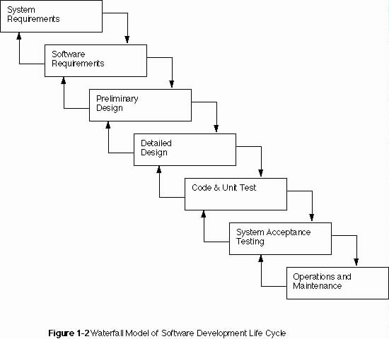
of prototyping in the form of a parallel step within requirements analysis. Boehm also states, however, that the waterfall is not particularly good for many types of systems, particularly interactive ones in which end-users participate in design activities. He attributes the failure of the waterfall for these types of systems not to a lack of iteration, but to the document-driven nature of the life cycle. Early users of the waterfall model employed written documentation almost exclusively for specification and communication of requirements and design between players in the development.
In addition to Boehm's observations regarding the waterfall, it is possible to make some other observations about the model. As can be seen in Figure 1-2, feedback is possible between adjacent stages, however, even this iteration is unlikely due to the massive investment in document production and eventually "pre-code" during large software development efforts. The expense associated with making changes at each level becomes greater as the life cycle progresses. Royce's original intent was probably to provide a mechanism to mitigate the risk of proceeding to the end of the development effort without having validated the results of the preceding steps, rather than to provide a planned iteration at each level. Iteration as described today is much more an active and interactive process. Also, Royce's introduction of prototyping at the requirements level was restricted to that level. No mention is made of the potential for uncovering hardware and software architectural problems via a prototype of the user interface, or the potential to iterate past one or more levels in order to alleviate the problem. With the waterfall, the likely solution for such occurrences is a work-around.
Mil-Std-490, DoD-Std-2167, and now DoD-Std-2167A are all
based on the waterfall model. Unfortunately, each of these standard life cycle
models have inherited many of the same problems.
1.3 Iterative Models of Software Development
In order to correct the problems associated with the waterfall model and to facilitate the communication of requirements between users, designers, and developers, life cycle models were developed for the purpose of allowing iteration and recursion during the course of design and development. Many of these attempts were oriented toward the goal of building systems which fulfill user's needs and provide accurate and valid requirements to developers for software design and coding activities.
Several iterative life cycles, most including some form of
prototyping have recently emerged. One of the very first iterative software
development life cycles employing prototyping was built around a set of tools
and was described by Wasserman and Shewmake (1982). They termed their approach
the User Software Engineering methodology with the following steps:
By the inclusion of Steps 5 and 9, "preliminary relational database design" and "implementation in PLAIN", Wasserman and Shewmake are making some rather broad assumptions regarding the nature of any system to be developed following the USE methodology, however, their early attempts at an integrated CASE environment and life cycle have matured into an extensive software engineering environment.
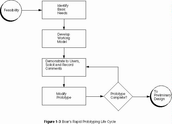
Another early model of iterative design for user requirements extraction and validation was outlined by Boar (1984). Figure 1-3 shows Boar's concept of iteration within a life cycle using rapid prototyping. As can be seen in Figure 1-3, Boar's model is
not a complete life cycle and ignores some important issues such as specification and software design. Although this is not the first iterative model described in the literature, it is probably one of the most widely referenced. Boar's strategy employs a throw-away approach to rapid prototyping in which the prototype is used for requirements definition and does not become the target system.
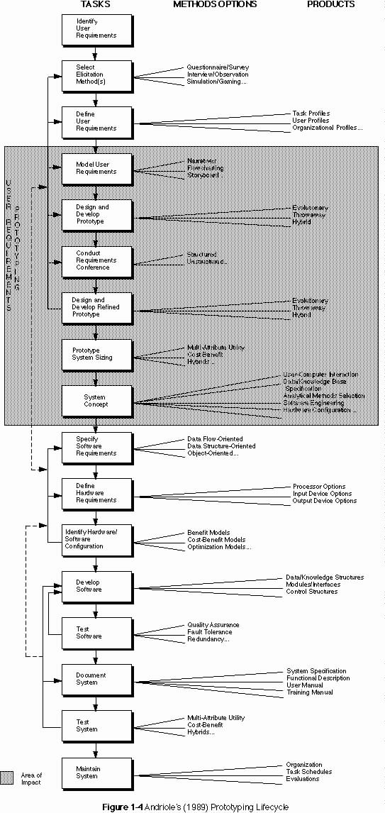
A more complete prototyping life cycle is given by Andriole (1989) and illustrated in Figure 1-4. Figure 1-4 shows a substantial portion of the life cycle devoted to user requirements prototyping. This model is specifically geared to the design and development of decision support systems, but appears to be applicable to many interactive information system development efforts. Comparing Figure 1-4 with Figure 1-2, it becomes clear that this and many other life cycle models are rooted in the waterfall. In contrast to the waterfall, however, Andriole's life cycle model forces attention to the issues which are severely neglected by the waterfall (e.g., user requirements, inter-level communication). In addition, this life cycle model employs a variety of tools and techniques which are oriented toward solving problems, as opposed to document production.
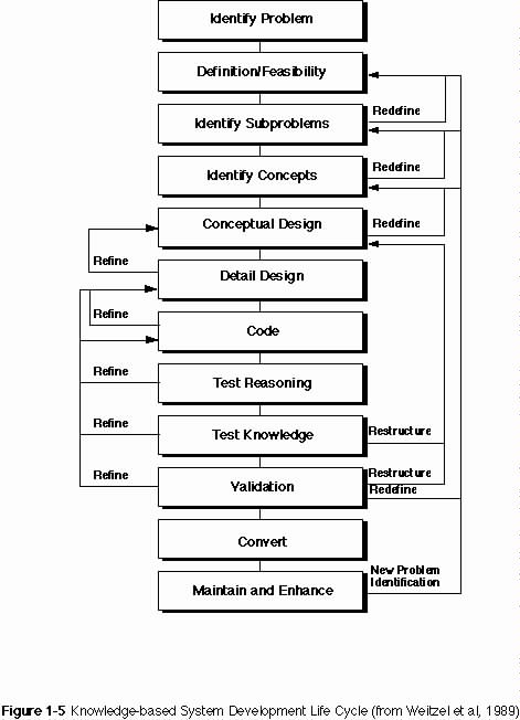
The realization that any life cycle must be tailored to the application under development is demonstrated by Weitzel and Kerschberg (1989). The knowledge-based system development life-cycle (KBSDLC) shown in Figure 1-5 is another prototyping-based software development life cycle used to build knowledge-based systems. Notice that two steps, "test reasoning" and "test knowledge" are unique to this application. The fact that these two steps have been added to what is otherwise basically a "waterfall-with-iteration" life cycle model is significant and illustrates that tailoring to a specific application or technology is often necessary.
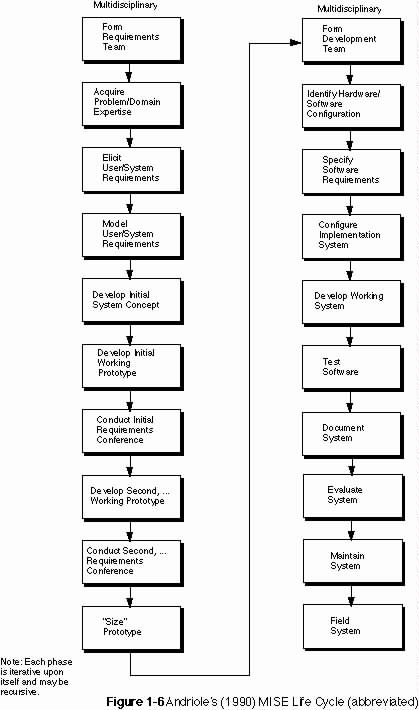
One of the latest software development life cycle models has been named the Multidisciplinary Information Systems Engineering life cycle model by Andriole (1990). This model is based on the premise that a life cycle is a living model with multiple disciplines and multiple, reconfigurable steps which are inherently iterative. The full model
is highly detailed, however, a simplified version is illustrated in Figure 1-6. This model employs a variety of rapid prototyping methods from "throw-away" to "evolutionary". This model is based on Andriole's (1989) earlier model, and like that model is founded in the waterfall. This model, however, provides even more opportunity to overcome the difficulties present in waterfall developments by instantiating even more levels of iteration, innovative specification and cross-level communication. A much more complete and detailed description of this life cycle can be found in Andriole's (1990) paper.
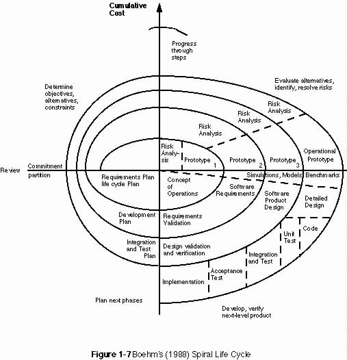
One of the most interesting departures from document-driven
life cycles is that of Boehm's (1988) spiral model of software development and
enhancement. This life cycle model is based on a risk-driven approach to
software development, but, according to Boehm, is capable of accommodating other
life cycle models as special cases of the spiral. Boehm asserts that his
approach allows evaluation of risk to drive which model is appropriate to follow
at any particular stage of the life cycle. The spiral model is illustrated in
Figure 1-7. Generally, a cycle of the spiral proceeds as follows:
2) Identify objectives of the of portion of the system being described and/or designed.
3) Identify alternative means of implementation.
4) Identify constraints imposed on the alternative implementations.
5) Evaluate alternatives with respect to objectives and constraints.
a) Identify areas of uncertainty which represent risk.
6) Formulate cost-effective strategy for resolving sources of risk (e.g., rapid prototyping, simulation, benchmarking, questionnaires, modeling or a combination of these)
7) Select development strategy based on remaining risks
a) rapid prototyping for user-interface risk
b) evolutionary development when low risk prototype is available
c) waterfall for strong program development or interface control risks
8) Complete cycle with review involving system stakeholders
a) test original hypothesis improvement of operational mission by software
1) check market factors, etc.
b) if hypothesis fails test, terminate spiral
c) otherwise spiral continues until product installation and operational test
d) break off additional spirals, if necessary to partition
development effort
Boehm (1988) arrived at a number of conclusions after having employed the spiral on the TRW Software Productivity System. First, the fact that the spiral is risk-driven rather than document- or code-driven suggests a particular adaptability to a wide range of software development efforts, particularly large ones. Secondly, the spiral has been successfully tested on a large development effort. Third, the spiral model needs further elaboration. Finally, and most importantly for this discussion, Boehm asserts that partial implementations of the spiral are adaptable to most current models and are particularly helpful in reducing project risk. Sage and Palmer (1990), however, state that the disadvantages of the spiral are exactly those features which are most useful in software development: i.e., massive iteration and continuous reassessment of products after each cycle.
Finally, the evolutionary prototyping life cycle model is
also becoming popular with some software developers and researchers.
Evolutionary prototyping involves the building of prototype software which
incrementally evolves into the final system (Gomaa, 1986). During the
evolutionary prototyping process, much more attention must be paid to
maintainability, reliability and robustness of software. Attention to these
issues during prototype development necessarily requires more time and effort,
leading to a greater inter-iteration interval. While the evolutionary
prototyping model does incorporate feedback and iteration, it can be expensive
and result in substantial investment only to proceed down an unfruitful path.
Boehm (1988) argues that evolutionary development is characteristic of the old
code-and-fix model of development with high risk difficulties of spaghetti code
and lack of planning. Evolutionary prototyping is appropriate, however, in some
development environments and has a number of proponents in the academic,
commercial and government communities (e.g., Andriole, 1990; Davis et al, 1988;
and Guimaraes, 1987). For an interesting method for comparing the various life
cycle models along several dimensions, see Davis (1988).
1.4 DoD-Std-2167A Software Development
The diagram most often associated with DoD-Std-2167A is shown in Figure 1-8 and is taken directly from page 10 of the Standard. On the surface, this figure has a strong resemblance to the waterfall. Standard management practice is mandated along with documentation requirements characteristic of the waterfall model. The figure caption accompanying the figure from the standard, however, is "Figure 1. An example of system
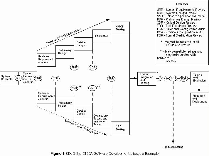
development reviews and audits." What this figure is apparently intended to show is the relationship of the general DoD-Std-2167A software development life cycle steps to the required list of reviews and audits (i.e., Mil-Std-1521) mandated by the standard. This is not necessarily, however, the precise nature of the model to be used by government contractors and software developers.
In paragraph 4.1.1, Software Development Process, the
standard mandates eight major activities as listed below. These activities
are:
It is interesting to note that 2167A specifically states that: "The software development process shall include the . . . major activities, which may overlap and may be applied iteratively or recursively". It would appear that, by this statement, the 2167A mandated life cycle is open to considerable interpretation, reorganization and negotiation as long as the major activities described above are included in the tailored model. Some general improvements over previous government standard life cycles can be seen. Paragraph 4.2.1 mandates the use of "systematic and well documented software development methods" during the life cycle. Paragraph 4.2.2 mandates the establishment of a "software engineering environment" which complies with contract security requirements. In addition, Paragraph 4.2.4 mandates contractor consideration of non-development software (NDS) for inclusion into the system where available, as long as the software is documented according to 2167A requirements. In addition, there are a variety of new requirements for development aids and software engineering methods which are not particularly germane to this discussion.
Specifically, under Paragraph 5.1.2 Software Engineering, the contractor is required to analyze the preliminary system specification to determine if the requirements are complete and consistent. This requirements may actually open the "contractual door" for a substantial iteration and rapid prototyping task. The standard continues at some length to describe those techniques, deliverables, reviews and audits required at each stage of the life cycle.
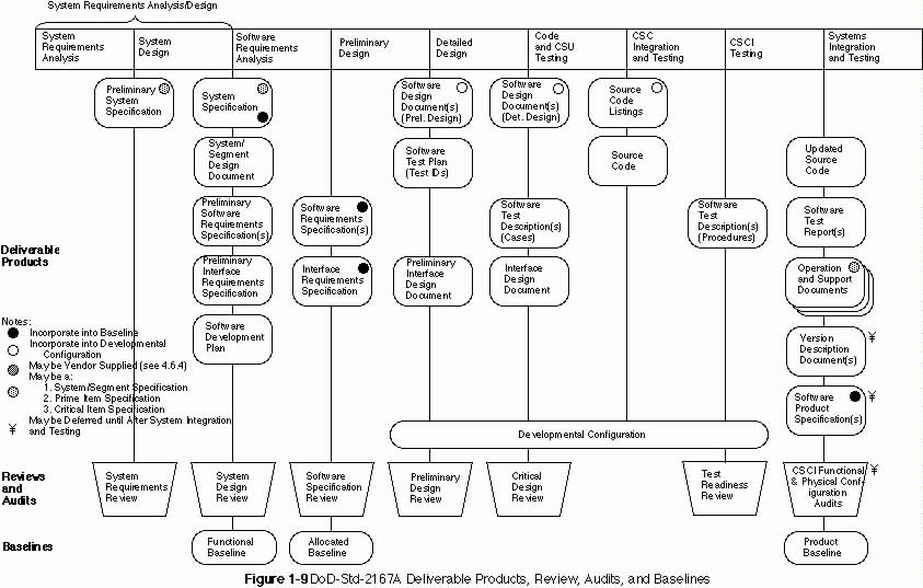
Figure 1-9 illustrates the deliverable products and their relationships to reviews, audits, and system baselines. In addition, a listing of Contract Data Requirements List (CDRL) titles and numbers of documentation is included in Appendix A. Looking at this figure enables the realization of precisly how similar the DoD-Std-2167A life cycle is to the
waterfall life cycle, and emphasizes the document-driven nature of both process models. This similarity warrants the same criticism that Boehm (1988) leveled at the waterfall; that
is, that fully elaborated documentation is inadequate completion criteria for early requirements and design phases for many classes of systems.
Can these obstacles to an iterative life cycle be overcome in the context of DoD-Std-2167A? Some researchers and some developers have responded to this challenge, and published alternative models which appear not to violate the standard's mandates.
2.0 ACCOMODATING ITERATION WITHIN DOD-STD-2167A
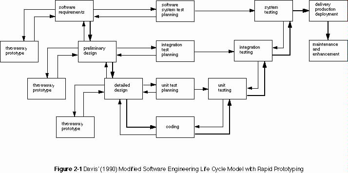
Several models of DoD-Std-2167A "iterative" life cycles have emerged which have challenged the notion that iterative development is impossible under the new standard. One such model is proposed by Davis (1990) in which throw-away rapid prototypes are employed at several levels of the life cycle for different purposes. Figure 2-1 illustrates the Davis model. Notice that using this approach, it is possible to complete each stage of the life cycle including reviews and deliverable documentation, while maintaining iteration and recursion within, if not across, stages.
If the Data Item Descriptions (DIDs) associated with 2167A are flexible enough to allow a liberal interpretation of deliverable documentation, that is to say, allow a rapid prototype, drawing, or model to be submitted as an "interactive" document, then some of the ill effects of document-driven life cycles may be remedied by using Davis' model. Data Items DI-CMAN-80008A (System/Segment Specification), DI-CMAN-XXXXX (System/Segment Design Document), DI-MCCR-80012A (Software Design Document), DI-MCCR-80025A (Software Requirements Specification), and DI-MCCR-80026A (Interface Requirements Specification) are all oriented toward textual descriptions of requirements and design, but explicitly allow graphical descriptions in some cases. Paragraph 10.2.7 Preparation for Delivery, of DI-CMAN-80008A, contains some language which may allow for the delivery of non-standard end-item descriptions (e.g., rapid prototypes, etc.). In addition, tailoring of most of these DIDs is allowed, with approval of the procuring organization.
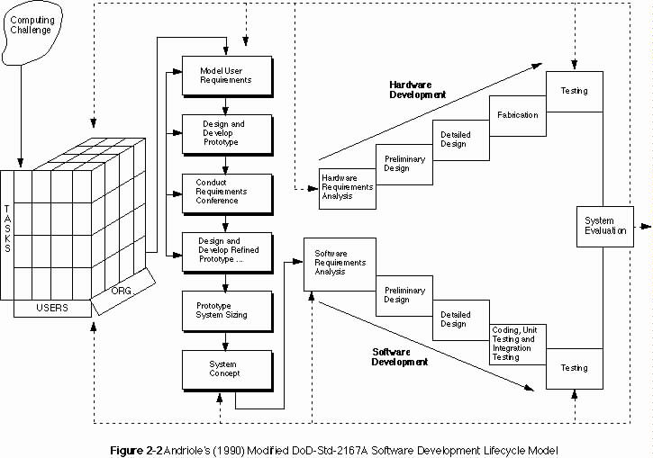
Another alternative model is proposed by Andriole (1990), which incorporates aspects of his earlier iterative prototyping life cycle into the 2167A life cycle. Figure 2-2 shows this model. Andriole suggests that this model is merely a bandaid for 2167A, and that a new requirements-driven, top-down life cycle is needed. As shown in Figure 2-2, most of the effective iteration in this modified model occurs on the front-end of the life cycle, with the remaining design and development stages following a waterfall approach.
Suppose that a design decision is made during preliminary or detailed design which impacts an earlier decision made during the requirements phase. Following this model, feedback would apparently not occur until system evaluation, at which time it would likely be too late to make an economical correction to the design.
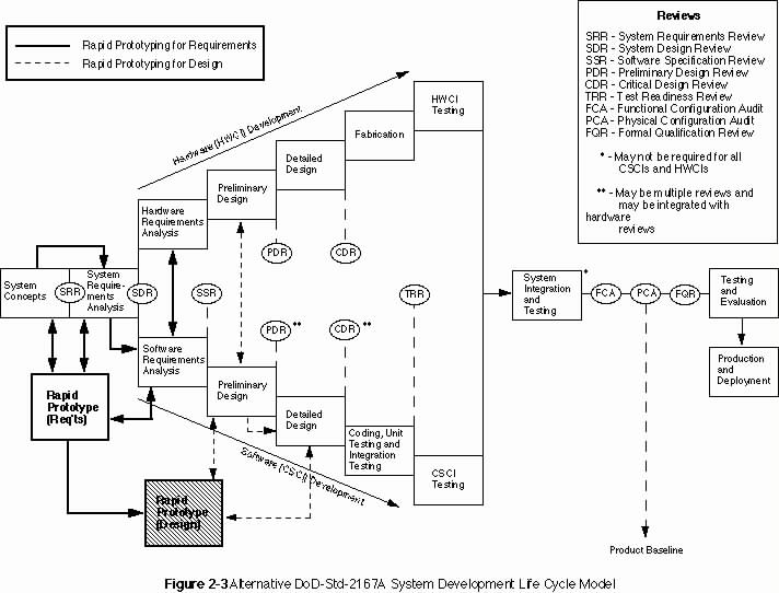
Consider the model proposed in Figure 2-3. This model contains some of the components of Davis' (1990) model, however, rapid prototyping commences much earlier, during system requirements activities. With this model, the prototyping and iterative requirements activities are initiated by the systems engineering organization acting on behalf of the operational organization for which the system is being procured. A preliminary prototype is constructed for the purpose of communicating and validating user's system-level requirements, and either this prototype or extracted requirements information is then passed along with the preliminary System/Segment Specification to the contracting organization(s). The developers then pick up the prototyping activity to aid in software requirements elicitation and validation, requirements are extracted from this version of the prototype and used to produce the Software Requirements Specification (DI-MCCR-80025A). This is followed by an iterative design prototyping effort during preliminary and detailed design. Nothing in this model is precluded from a DoD-Std-2167A development effort, except as explicitly excluded by the development contract. In fact, even though this model remains essentially document driven, it is possible to agree upon additional, alternative documentation which require evidence of the completion of a variety of requirements and design-oriented tasks, rather than traditional text and diagrams.
While DoD-Std-2167A appears to conform for the most part to the waterfall model, several researchers have developed models which conform to the new standard, while introducing modern concepts of iterative requirements and design. Recall that Royce (1970) initially introduced the concepts of limited iteration and prototyping as enhancements to the waterfall model. The fact that the waterfall and 2167A are both document-driven standards, which Boehm (1988) has condemned as counter-productive to system developments which are highly interactive, can work both for and against iteration and rapid prototyping, depending on the requirements for the documents to be delivered. This limitation also depends on the source of the CDRL Data Items.
Often times, software developers fail to recognize the potential impact of documentation requirements which may be invoked for system developments via specifications and standards from other disciplines. One particularly appropriate example of an associated discipline is that of human factors engineering. Human factors psychologists and engineers have been performing research and participating in system and software development for many years with special attention to end-users, their tasks, and their performance while executing those tasks. For example, specification Mil-H-46855B (Human Engineering Requirements for Military Systems, Equipment and Facilities) and the associated Mil-Std-1472D (Human Engineering Design Criteria for Military Systems, Equipment and Facilities) have a rather long list of data items which, when invoked, require many of the analyses, design and documentation activities needed in an iterative software development life cycle. The Critical Task Analysis Report (CTAR, DI-H-7055), the Human Engineering Design Approach Document - Operator (HEDAD-O, DI-H-7056), and the Human Engineering Dynamic Simulation Plan (HEDSP, DI-H-7052), mandate user-centered requirements analysis and design tasking. If used in concert with DoD-Std-2167A, almost any reasonable life cycle model may be derived, when contracting and government program offices agree. The only model which is not easily derivable from 2167A is the evolutionary model.
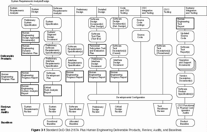
As an example of how these additional deliverable documents might be used, Melde, Overmyer, and Trowbridge (1985) recently demonstrated how rapid prototyping and system simulation can be used together in the design of a large-scale interactive information system. These activities were implemented very early in the software development lifecycle and had a direct impact on the hardware and software architecture, user-system interface design, and operations concept of the system under development. This is typical of how such activities may be mandated, performed, documented and evaluated on a contract. Figure 3-1 shows how some of the human factors engineering data items might be required in the context of the DoD-Std-2167A deliverable products schedule, relative to the software development life cycle stages. Guidance on the performance of those tasks which underly these DIDs may be found in AFAMRL-TR-81-35, Human Engineering Procedures Guide and in AFSC DH 1-3, AFSC Design Handbook 1-3, Human Factors Engineering, and other related military and civilian documents.
These data items and associated tasks have been available as CDRL items since the late 1970s and may be used as leverage to force iterative, user-centered tasking. A listing of these Data Item Descriptions, which can be selectively required by invoking Mil-H-46855B, can be found in Appendix B. An excellent example of Statement of Work (SOW) language for invoking these specifications, standards and DIDs is given by S. L. Smith in ESD-TR-84-158.
Finally, it is clear that DoD-Std-2167A was not specifically developed with iterative design in mind, even though iteration is specifically mentioned in Paragraph 4.1.1. Regardless, it has been shown that iterative requirements analysis, software design, and system development may be performed under DoD-Std-2167A, if contractors and government procurment officers take the time, up front, to tailor the life cycle for each major system development effort.
AFAMRL-TR-81-35 (September, 1981) Human Engineering
Procedures Guide, Wright Patterson Air Force Base, OH 45433: Armstrong
Aerospace Medical Research Laboratory.
AFSC DH 1-3 (June, 1980) AFSC Design Handbook 1-3, Human
Factors Engineering, Andrews Air Force Base, DC 20334: Air Force Systems
Command.
Andriole, S.J. (1990) Information System Design
Principles for the 90s: Getting it right!, Fairfax, VA: AFCEA
International Press.
Andriole, S.J. (1989) Storyboard Prototyping: A New
Approach to User Requirements Analysis., Wellesley, MA: QED Information
Sciences, Inc.
Boar, B.H. (1984) Application Prototyping: A Requirements
Definition Strategy for the 80s, New York, NY:
Wiley-Interscience.
Boehm, B.W. (1988, May) A spiral model of of software
development and enhancement, Computer, 61-72.
Boehm, B.W. (1987, September) Improving software
productivity, Computer, 61-72.
Davis, A.M. (1990) Software Requirements: Analysis and
Specification. Englewood Cliffs, N.J.: Prentice-Hall.
Davis, A.M., Bersoff, E.H., and Comer, E.R. (1988) A strategy for comparing alternative software development life cycle models, IEEE Transactions on Software Engineering, 14(10), 1453-1461.
DOD-STD-2167A (1988, February) Military Standard: Defense
System Software Development , Washington, D.C.: Department of
Defense.
DOD-STD-2168 (1988) Military Standard: Defense System
Software Quality Program, Washington, D.C.: Department of
Defense.
ESD-TR-84-158 (April, 1984) User-System Interface Design
in System Acquisition (S. L. Smith), Hanscom Air Force Base, MA 01731: Air
Force Electronic Systems Division.
Gomaa, H. (1986) Prototypes - Keep them or throw them away?
In M. Lipp, Ed. Infotech State of the Art Report on Prototyping, Oxford,
England: Pergamon Infotech Ltd., pp 43-54.
Guimaraes, T. (1987, December 1) Prototyping: Orchestrating
for success, Datamation, 101-106.
Melde, J.E., Overmyer, S.P. and Trowbridge, T.L. (1985,
March) Simulation and display prototyping in the design of man-machine systems.
In Proceedings of the Eighteenth Annual Simulation Symposium (pp.
235-253) Tampa, FL: Society for Computer Simulation.
MIL-H-46855B (1979, January) Military Specification:
Human Engineering Requirements for Military Systems, Equipment and
Facilities, Washington, D.C., Department of Defense.
MIL-STD-490A Specification Practices, Washington,
D.C.: Department of Defense.
MIL-STD-1521B Technical Reviews and Audits for Systems,
Equipments, and Computer Software, Washington, D.C.: Department of
Defense.
Royce, W.W. (1970, August) Managing the development of
large software systems: Concepts and Techniques, . In Proceedings of WESCON,
1-9.
Sage, A.P. and Palmer, J.D. (1990) Software Systems
Engineering. New York, N.Y.: Wiley.
Wasserman, A.I. and Shewmake, D.T. (1982) Rapid prototyping
of interactive information systems, ACM SIGSOFT Engineering Information
Notes, 7(4), 171-180.
Weitzel, J.R. and Kerschberg, L. (1989) A system development methodology for knowledge-based systems, IEEE Transactions on Systems, Man, and Cybernetics, 19(3), 598-605.
DID TITLE DID NUMBER
System/Segment Specification DI-CMAN-80008A
System/Segment Design Document DI-CMAN-XXXXX
Software Design Document DI-MCCR-80012A
Version Description Document DI-MCCR-80013A
Software Test Plan DI-MCCR-80014A
Software Test Description DI-MCCR-80015A
Software Test Report DI-MCCR-80017A
Computer system Operator's Manual DI-MCCR-80018A
Software User's Manual DI-MCCR-80019A
Software Programmer's Manual DI-MCCR-80021A
Firmware Support Manual DI-MCCR-80022A
Computer Resources Integrated Support Document DI-MCCR-80024A
Software Requirements Specification DI-MCCR-80025A
Interface Requirements Specification DI-MCCR-80026A
Interface Design Document DI-MCCR-80027A
Software Product Specification DI-MCCR-80029A
Software Development Plan DI-MCCR-80030A
Software Quality Program Plan (DOD-STD-2168) DI-MCCR-XXXXX
DID TITLE DID NUMBER
Personnel Subsystem/Human Factors DI-H-3251 (1971)
Development Plan (HFDP)
Personnel Subsystem Test and Evaluation (PSTE) Plan DI-H-3272 (1970)
Human Engineering Program Plan (HEPP) DI-H-7051 (1979)
Human Engineering Dynamic Simulation Plan (HEDSP) DI-H-7052 (1979)
Human Engineering Test Plan (HETP) DI-H-7053 (1979)
Human Engineering System Analysis Report (HESAR) DI-H-7054 (1979)
Critical Task Analysis Report (CTAR) DI-H-7055 (1979)
Human Engineering Design Approach Document - DI-H-7056 (1979)
Operator (HEDAD-O)
Human Engineering Design Approach Document - DI-H-7057 (1979)
Maintainer (HEDAD-M)
Human Engineering Test Report (HETR) DI-H-7058 (1979)
Human Engineering Progress Report (HEPR) DI-H-7059 (1979)